- Products
- Automotive Tester
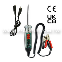
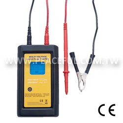
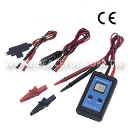
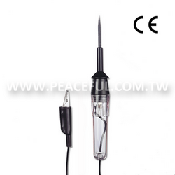
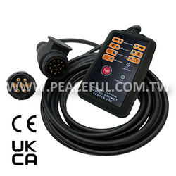
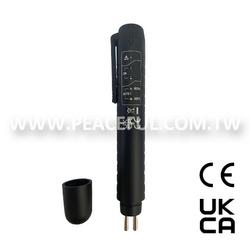
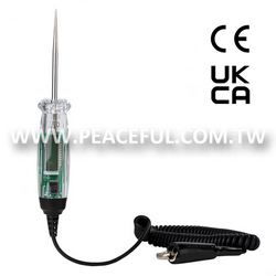
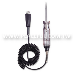
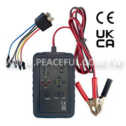
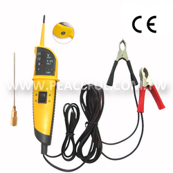
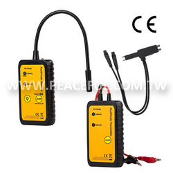
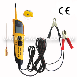
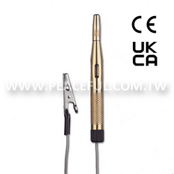
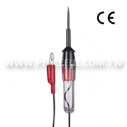
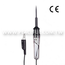
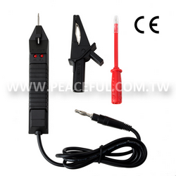
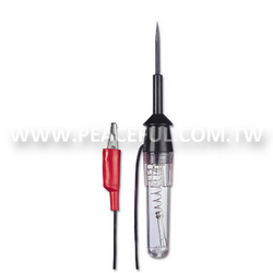
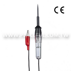
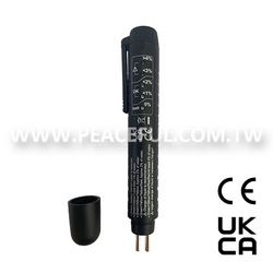
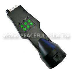
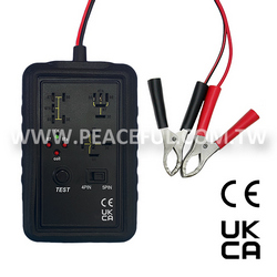
- Multi Function Automobile Tester
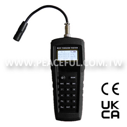
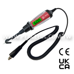
6522Multi Function Automobile Tester
Descriptions:
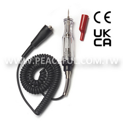
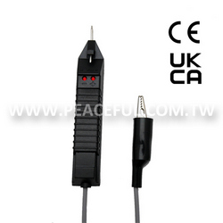
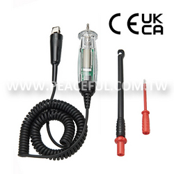
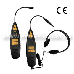
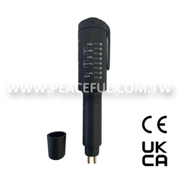
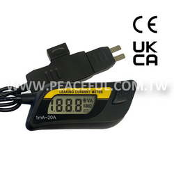
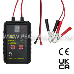
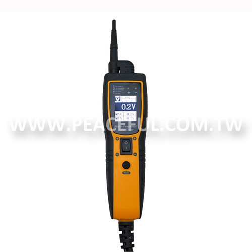
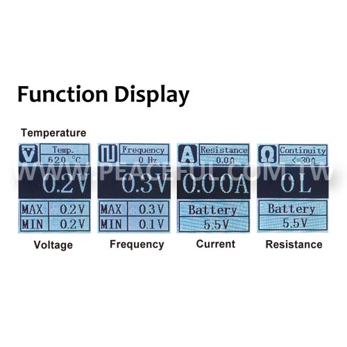
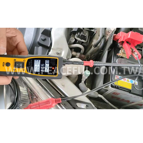
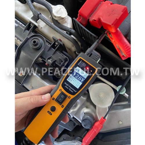
The multi-function automobile tester has LCD display to indicate the measured result. It has polarity detection with the LEDs for a positive and negative indication of DC voltage. For auto use, the functions included the measurement of DC voltage and current, signal frequency and max/min voltage, resistance, temperature and power providing testing.
Features:
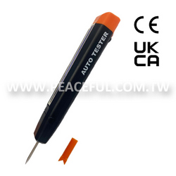
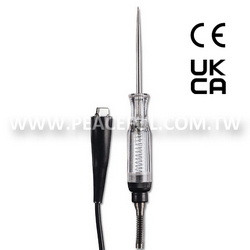
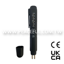
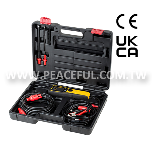
- With CE and UKCA Approvals.
- Clearly LCD Display.
- Illumination.
- DC Voltage Measurement.
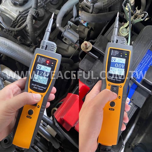
- Signal Frequency and Max / Min Voltage Measurement
- Resistance Measurement.
- Current Measurement.
- Power Providing Test.
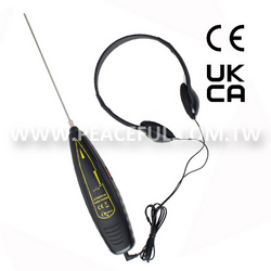
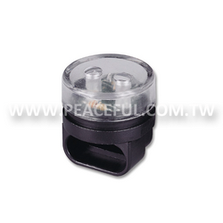
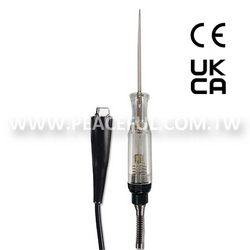
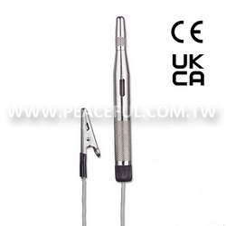
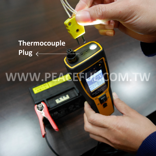
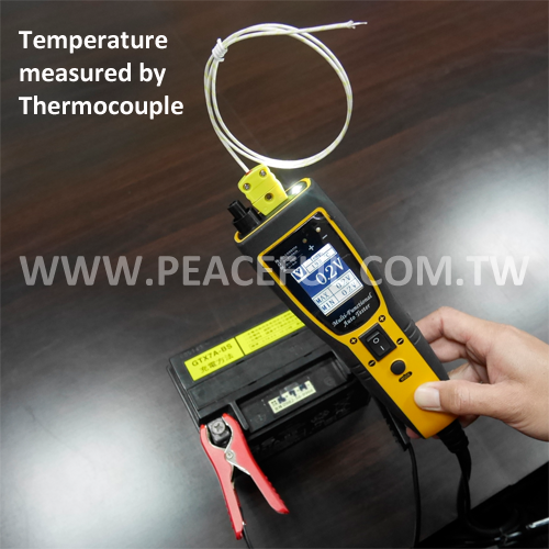
- With accessories of thermocouple and for temperature measurement.
- Patented.

Specifications:
| MEASUREMENT | ||
|---|---|---|
| SUPPLY VOLTAGE | 12-24V DC System | |
| VOLTAGE MEASUREMENT RANGE | 0-70V | |
| DC CURRENT MEASUREMENT RANGE | 0-5A DC | |
| FREQUENCY MEASUREMENT RANGE | 0-300KHz (Square Wave) | |
| RESISTANCE MEASUREMENT RANGE | 0-200KΩ | |
| OPERATING ENVIRONMENT | ||
| WORKING TEMPERATURE | 0-50°C | |
| STORAGE TEMPERATURE | -10-60°C | |
| WORKING HUMIDITY | ≤ 85% | |
| MEASURED TEMPERATURE RANGE | -50-500°C / -58-932°F (The display will appear ERROR when tester is not connected with temperature probe.) CAUTION: The table indicates the maximum reading range of the tester, user has to select corresponding K-type thermocouple for different temperature measurement. |
|
| TEMPERATURE | TEMP. SENSOR | TESTING TEMP. |
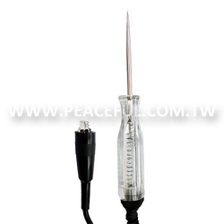
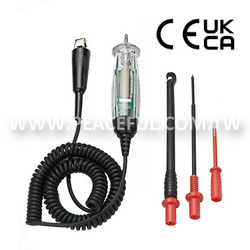
| MEASUREMENT | Testing Probe | ≦150°C / 302°F |
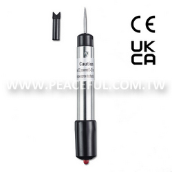
| Thermocouple (3535A) | -50°C~205°C/-58°F~401°F | |
| ACCURACY | ||
| DC VOLTAGE | 0-70V ± (2%+2digits) | |
| SIGNAL FREQUENCY | 0-300KHz ± (1%+1digit) | |
| RESISTANCE | 0-200K ± (5%+3digits) | |
| DC CURRENT | 0-5A ± (3%+10digits) | |
| TEMPERATURE | -50~-20°C (±1.5%+4digits) -20~500°C (±1.5%+3digits) -58~-4°F (±1.5+6digits) -4~932°F (±1.5+5digits) |
|
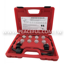
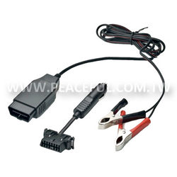
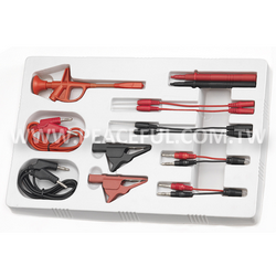
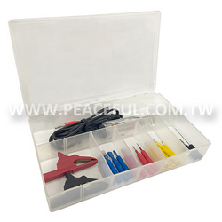
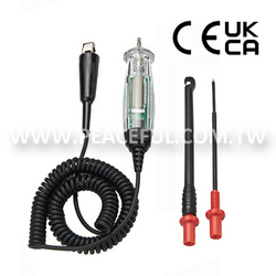
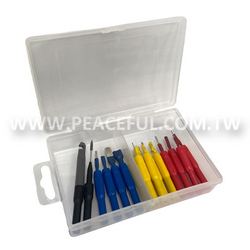
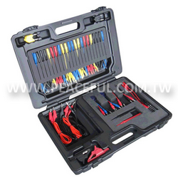
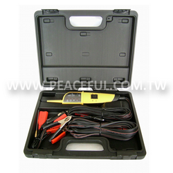
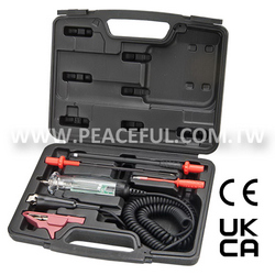
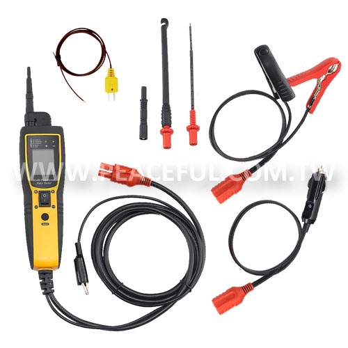
| ACCESSORY | ||
| STANDARD |
|
|
| OPTIONAL |
|
|
| INSTRUCTIONS | ||
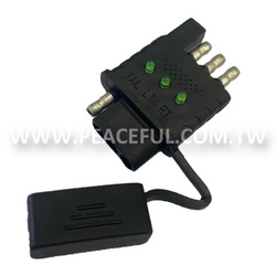
| Shortly press MODE button to switch function between DC voltage, signal frequency measurement, resistance and DC current. Connect the red clip to positive of battery and black clip to negative of battery. Auxiliary ground connector is used to connect with the negative of testing object when it is necessary. | ||
DC VOLTAGE MEASUREMENT
|
||
SIGNAL FREQUENCY and MAX / MIN VOLTAGE MEASUREMENT
|
||
RESISTANCE MEASUREMENT
|
||
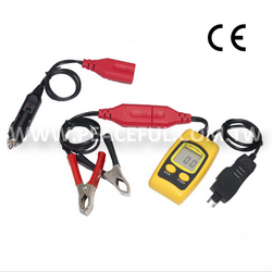
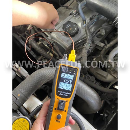
| DC CURRENT MEASUREMENT There are two methods to measure the current: METHOD 1 Providing Current to External
|
||
METHOD 2
|
||
TESTING POWER PROVIDING
|
||
| TEMPERATURE MEASUREMENT Application of different temperature probe
|
||
| CAUTION: During the power providing, if the short circuit protection has activated, the PPTC fuse will jump off, and it will self-recover within about 60 seconds. Please do not touch the testing probe when short circuit protection is activated because high temperature generally comes with short circuit. |
||