- Products
- Electrical
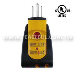
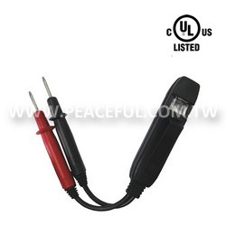
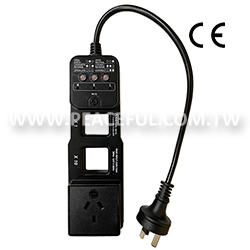
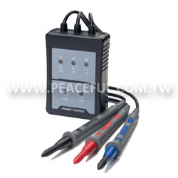
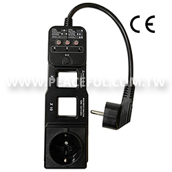
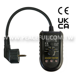
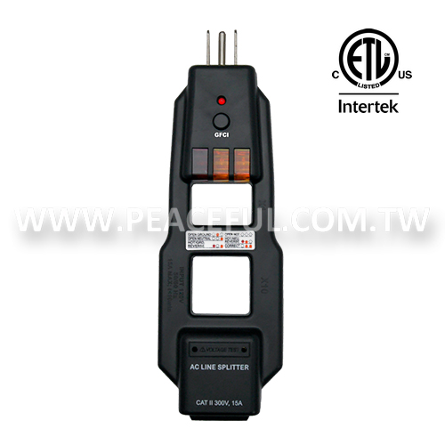
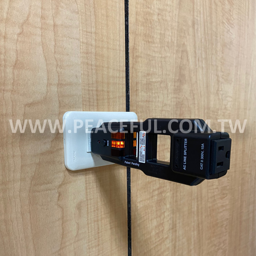
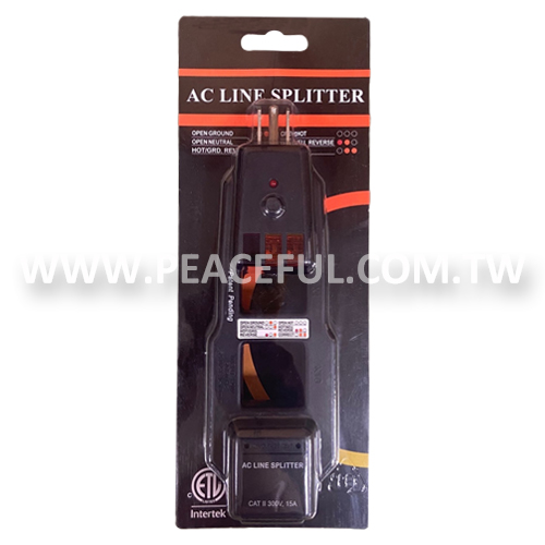
- AC Line Splitter
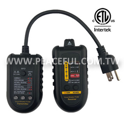
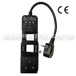
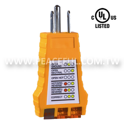
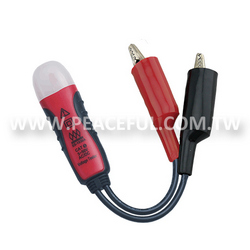
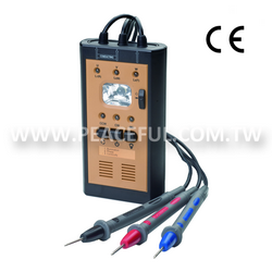
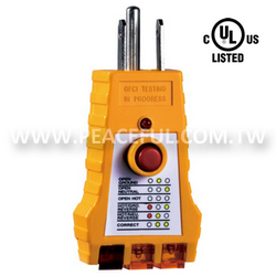
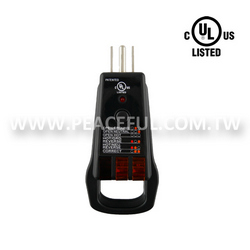
1937AC Line Splitter
Descriptions:
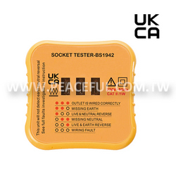
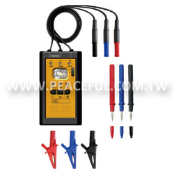
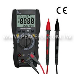
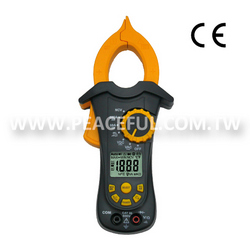
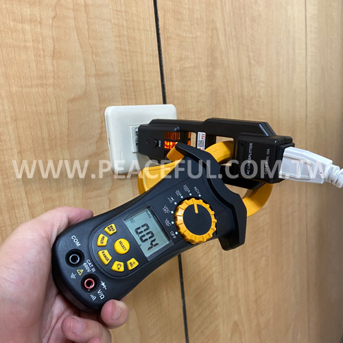
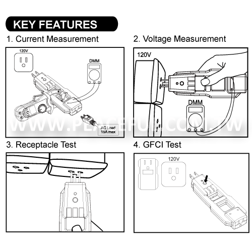
The AC line splitter is a helpful testing device for electrician. Electrician can measure the current with clamp meter through the X1 and X10 measuring rings. X1 is 1:1 measurement, and X10 is ten times (1:10) of the actual current, which is helpful for small current measurement. This device also combines the function of socket tester and GFCI tester, which means electrician can use this tester to test socket and load at the same time.
Features:
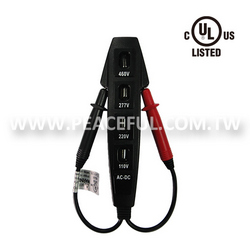
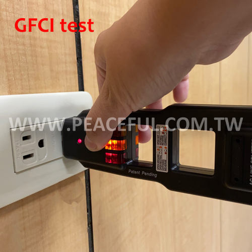
- Detect faulty wiring in 3 wire receptacle.
- Test for GFCI receptacle for proper operation, 110-125V circuits.
- Various combinations of three lights tell if wiring is correct or six possible faulty conditions.
- Measure the current with clamp meter through the X1 and X10.
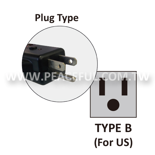
- Plug Type: TYPE B for US
- Patented.

Specifications:
| MEASUREMENT | |
|---|---|
| INPUT VOLTAGE | 120V ± 10% |
| CURRENT | Maximum 15A |
| OPERATING TEMPERATURE | 5 ~ 40°C (41 ~ 104°F) |
| STORAGE TEMPERATURE | -20 ~ 60°C (-4 ~ 140°F) |
| OPERATING HUMIDITY | Max 80% with temperature up to 30°C (86°F); linearly decreasing to 50% at temperature 40°C (104°F) |
| STORAGE HUMIDITY | <80% |
| ALTITUDE | <2000m (7000ft) |
| SAFETY CATEGORY | CAT II 300V |
| INSTRUCTION | |
|
A. CURRENT MEASUREMENT |
|
|
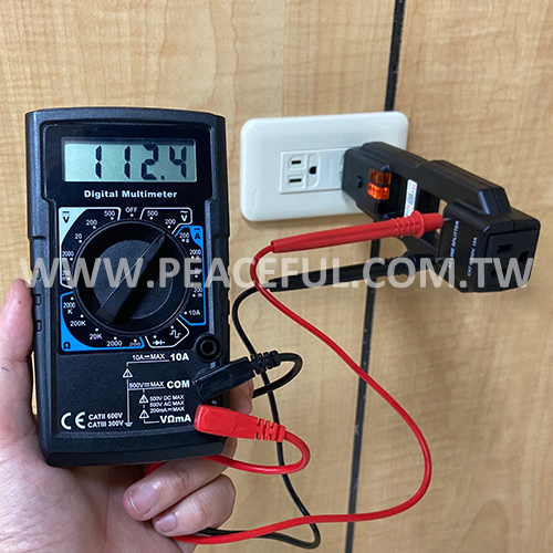
B. VOLTAGE MEASUREMENT |
|
|
C. RECEPTACLE TEST |
|
|
D. GFCI TEST |
|